.jpg) As
you can see, this reactor consists of a main outer shell, through
which pipes are inserted parallel to the axis.
As
you can see, this reactor consists of a main outer shell, through
which pipes are inserted parallel to the axis.Alternate Reactor Designs
The
reactor chamber volume's main purpose is to transfer heat from the
heat source (LP burner, fuel-oil, or residual reactor gases) into the
biomass through the use of a intermediate, flowable media.
My first thoughts along this line are indicated by the cut-away figure below:
As
you can see, this reactor consists of a main outer shell, through
which pipes are inserted parallel to the axis.
The heat source gases flow through the center of the pipes, heating them. The volume inside the cylinder (and outside the pipes) is filled with a fine, sifted sand. This sand serves to transfer the heat from the pipes to the biomass.
The biomass would be introduced through the outside wall of the cylinder, at the bottom. Upon coming in contact with the hot sand, flash pyrolysis will take place, producing gas. This pyrolysis gas will occupy a far larger volume than the original biomass, creating bubbles, or voids in the sand. The bubbles, being lighter than the sand, will travel upward, dragging sand along with them. The flow will be a 3-dimensional bubbler, with bubbles rising in the center, carrying sand, and the sand returning downward along the outside, along the pipes.
But what if this doesn't lead to good enough heat transfer? What if the sand in the 'corner' areas just sits there, and doesn't contribute to the heat transfer, or worse yet, creates local 'hot-spots'?
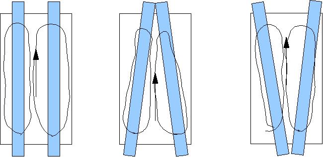
Well, there are other geometries that can be chosen, how about angling the heating pipes?
.jpg) Here
we have the pipes clustered together on one end,and out at the
perimeter on the other.
Here
we have the pipes clustered together on one end,and out at the
perimeter on the other.
In the configuration shown, the returning sand would tend to follow the pipes on the way down, spreading towards the perimeter as it comes down.
Alternatively, this assembly could be turned upside-down, and the biomass admitted on the centrally-bunched end. In this case, the sand would tend to drift towards the center as it came back down.
Which way is better? I am not sure. I would probably build the straight-pipe version, and see how it worked, going to more elaborate designs if shortcomings were noticed.
Flows I think would develop in the two configurations:
Another design idea I have been thinking about involves not the use of the combustion gases alone on the 'hot' side of the reactor, but rather have the 'hot' side be a fluidized bed:
Specifically, the use of a fluidized bed, utilizing fuel of any type (biomass, bio-oil, propane, other hydrocarbons, etc) and air, to provide the heat to the reactor chamber proper. The reactor itself would reside inside the fluidized bed that is providing the process heat.
A pictorial representation of the device follows:
The
above embodiment improves on previous designs because it has a
higher coefficient of heat transfer between the heating and heated
portions of the reactor. Rather than the Gas->metal->sand heat
path, we now have a sand->metal->sand path, greatly increasing
the heat transfer characteristics.
The design operates in this fashion:
Air and fuel are admitted into the outer jacket, forced into the hot sand zone, which is kept above the ignition temperature of the 'fuel'
The combustion of the 'fuel', in conjunction with the flow inherent in the 'air-in' serves to fluidize the outer jacket of the reactor, forcing product gases and sand upward through the pipes inside the inner reactor.
The hot outer jacket sand/gas/fuel mixture dumps heat into the inner chamber through conduction and radiation.
This design can be applied in any instance where 'process' heat sources must be kept from physically mixing with the process reactants, and heat transfer coefficients must be kept high.
Prior ideas:
Jim Frederick, of the Georgia Institute of Technology on May 18, 2006 outlined a 'FERCO/SilvaGas Double Fluidized Bed Reactor' embodying similar ideas of separate heating and reaction zones.
Revision : 31 Date: 2006/08/21 21:01:53